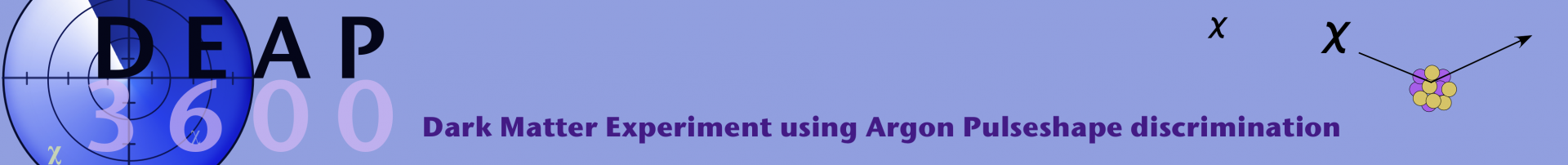
Fig. 1: DEAP-3600 Schematic
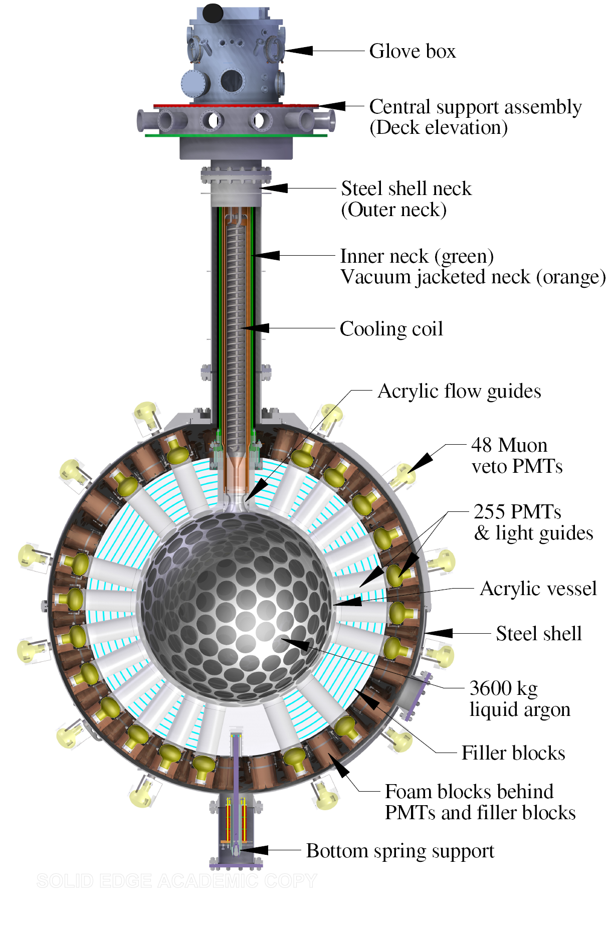
Fig. 2: Steel Shell with Veto PMTs
It seems counter-intuitive to install yourself 2 km underground to solve one of the biggest mysteries that exists far out in space, but that is exactly what the DEAP collaboration team has done. Why go to this extreme to protect DEAP-3600 from the outside world? The answer in a word: sensitivity. As a dark matter detector, DEAP-3600 is so sensitive that it must be shielded as much as possible from all other particles that fall to the earth’s surface from space or enter the laboratory from outside. With these precautions in place, now this ultra-sensitive detector is poised to target dark matter.
How sensitive is DEAP-3600? DEAP-3600 has the sensitivity to spin-independent WIMP-nucleon scatters with cross-sections as low as 10-46 cm2 per nucleon, about a factor of twenty beyond current sensitivity. This sensitivity comes not only from being installed deep underground, but also from DEAP-3600’s design.
The conceptual design of the central parts of the DEAP-3600 detector is shown on the left (Fig. 1). The 2-inch thick acrylic vessel with inner radius of 85 cm serves as the primary containment for the 3.6 tons of liquid argon, held at close to -180 degrees Celcius. The inside is coated with tetraphenyl butadiene (TPB, C28H22) wavelength shifter to shift the ultraviolet (UV) light generated by argon scintillation to the visible region, which can then be transmitted to the photomultiplier tubes (PMTs) through the acrylic. DEAP-3600 uses 255 8-inch-in-diameter Hamamatsu R5912 high quantum efficiency (HQE) PMTs.
The PMTs are separated from the AV through acrylic light guides and polyethylene filler blocks, providing neutron shielding and thermal insulation. The inner detector is housed in a large stainless steel shell (Fig. 2), which itself is immersed in an 8-meter diameter ultra pure water tank and instrumented with veto PMTs, serving as a radiation shield and Cerenkov veto for cosmogenic muons. The acrylic neck serves to allow access to the interior of the vessel and the glove box allows insertion or extraction of the process systems, resurfacer, TPB deployment system, and calibration sources in a radon-free environment.
An event in DEAP-3600 starts with the creation of excited argon dimers either from the nuclear recoil of argon itself, atomic excitation of argon from electromagnetic events, alpha particles, or the recoil of heavy nuclei. The excited dimers decay and produce UV light at a wavelength of 128 nm. The liquid argon is transparent to the UV light which excites the TPB. The light emitted by the TPB is detected by the PMTs. The PMT signals are split and amplified into high-gain and low-gain channels. The signals are read out by waveform digitizers (CAEN V1720 for the high-gain and CAEN V1740 for the low-gain). A flexible data acquisition system allows recording of the PMT signals.
Fig. 3: Schematic of Resurfacer
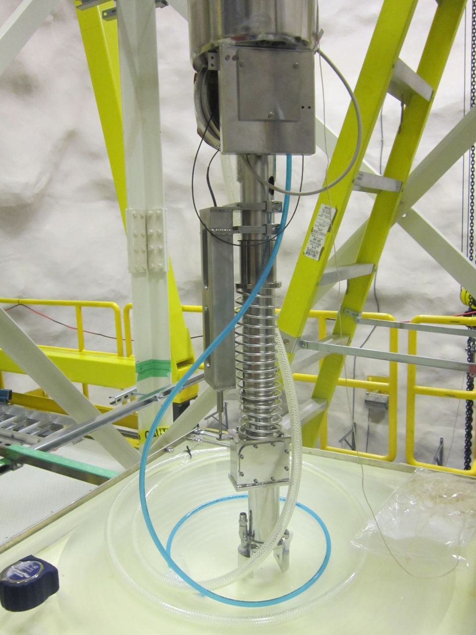
Fig. 5: Resurfacer Test Sanding
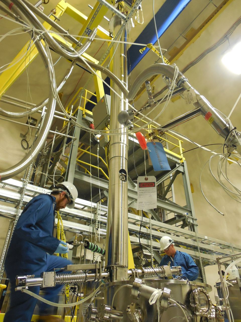
Fig. 4: Resurfacer Commissioning at SNOLAB
A resurfacing device (see Fig. 3) is designed to remove the inner surface layer of the spherical acrylic vessel, which has been exposed to radon-laden air during construction. It is deployed through the vessel neck and operated with the detector volume hermetically sealed from the lab and continuously purged with purified nitrogen gas. The resurfacer is extracted through the glove box and into an extraction canister. During extraction, the detector, glove box, and extraction canister maintain purge flow and are hermetically sealed from the lab. The resurfacer is designed to remove up to 1 mm of acrylic or TPB-coated acrylic, and operates by sanding action with continuous water flush. Sediment created during sanding is continuously extracted through a suction line adjacent to the sanding head. The materials used in the fabrication of the resurfacer are of low radioactivity. Stainless steel is used for all mechanical housings, due to its cleanliness and resistance to corrosion (Fig. 4 and 5).
After sanding of the surface layer is completed, the sanding heads are retracted, and the acrylic surface is flushed many times with water to extract remaining loose material. The resurfacing of the AV happened in September-November 2014.
The vessel is then flushed with nitrogen gas to allow drying, after which pumped down to vacuum. The TPB wavelength shifter deposition source is deployed in the center of the vessel and heated to high temperature to allow water vapor in the acrylic to outgas. TPB is then loaded into the source, heated and evaporated onto the acrylic vessel. This happened in June 2015.
The cryogenic requirements of DEAP will be met through the use of liquid nitrogen, which is gravity fed from a large dewar on top of the experimental hall to the cooling coils in the detector neck. Boil-off N2 is collected and returned to the dewar where it is recondensed by cryocoolers. Liquid argon is held either in a large storage dewar or inside the detector. The cryogenics operates in a stable closed loop and is controlled by an industrial DeltaV system.
In order to reduce the risk of accidental contamination, the detector is calibrated using a combination of external neutron sources, external and internal optical calibration systems, and internal backgrounds, such as 39Ar betas and residual surface backgrounds. The water tank is equipped with three vertical calibration tubes that allow for periodic deployment of a tagged Am-Be neutron source at the equator of the steel shell. Gamma calibrations are performed with a tagged 22Na source moved through an additional circular tube installed vertically around the steel shell. The optical calibration systems consist of 20 LED-driven optical fibers for light injection, attached to selected light guides. In addition to this, an internal diffuse and isotropic light source is used to characterize in detail the detector response at chosen wavelengths before cooling down the detector both before and after the TPB deposition.